Switching Power Supply 120PS
- Power – up to 120 W
- Mounting – DIN rail or screw mounting
- Regulated output voltage
- Output voltage 12 V or 24 V
- Input – terminal block
- Output – terminal block
- IP20 protection rating
- Terminal protection rating IP00
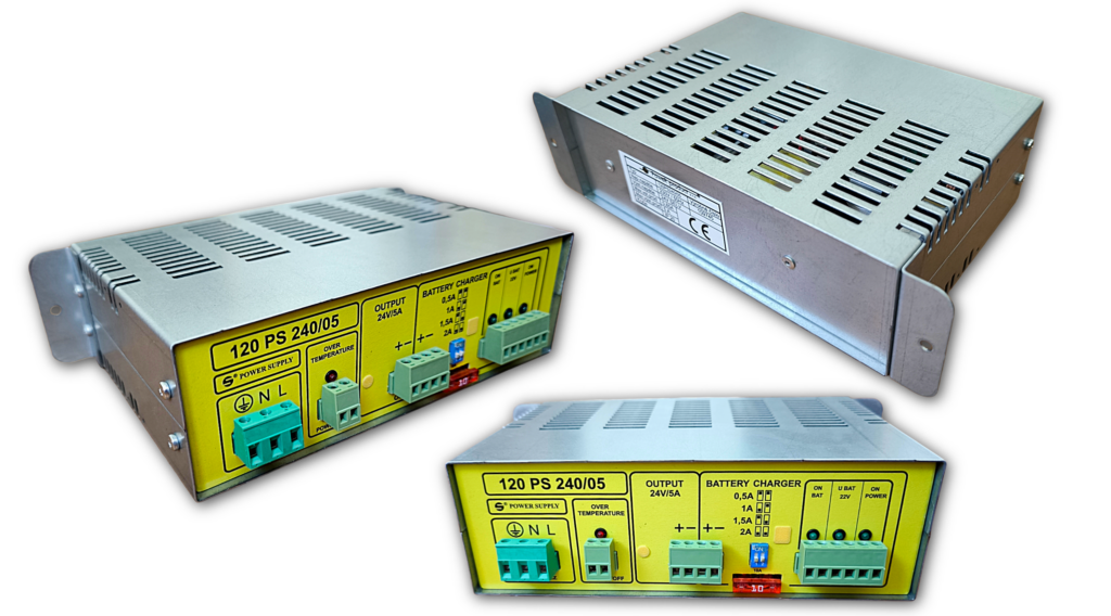
The 120PS series stabilized power supplies are Safety Extra Low Voltage (SELV) sources designed primarily for powering electrical systems. They are intended for use with lead-acid batteries, with which they form a comprehensive backup power system with multiple functions. The power supplies maintain an output voltage of 12 V (or 24 V) even while charging the battery at an elevated voltage. The output voltage of the unit never exceeds 12 V (or 24 V). As long as the mains voltage is present, the power supply provides power to the connected security system while simultaneously keeping the backup battery in a charged state. The voltage at the power supply output (OUTPUT) is 12 V (24 V). The ON BAT, U BAT 11V, and ON POWER LEDs are illuminated. The signaling contacts for ON BAT, U BAT 11V, and ON POWER are closed. In the event of a mains power failure, the OUTPUT terminals maintain a voltage of 12 V (24 V) from the backup battery via a linear stabilizer. This state is indicated by the ON POWER LED turning off and the opening of the ON POWER contact. Depending on the voltage drop of the battery, the output voltage gradually decreases. | |
If the power failure is prolonged, the battery voltage gradually decreases. A drop below 11 V (22 V) is indicated by the U BAT 11V LED turning off and the opening of the U BAT 11V contact. If the mains power failure continues and there is a risk of damaging the battery through deep discharge, the battery will be disconnected, and the security system will no longer be powered. Disconnection occurs when the battery voltage drops below 10.5 V (21 V). This state is indicated by the ON BAT LED turning off and the opening of the ON BAT contact. Once the mains voltage is restored, the power supply takes over the load, and the backup battery is reconnected for charging. The maximum battery charging current is set via DIP switches. The available settings are 4 A, 3 A, 2 A, 1 A (2 A, 1.5 A, 1 A, 0.5 A). When the voltage at the battery terminals reaches 13.8 V (27.6 V), the battery continues to be charged at a constant voltage. By closing the POWER OFF terminals, the power supply is electronically switched off, and the system is powered solely by the backup battery. This controlled state is intended for testing the backup battery. The need for battery replacement can then be assessed based on the backup duration. | |
Table 1: Technical parameters
| Input Voltage | 195 V to 255 V / 50 Hz |
| Maximum power consumption | 180 VA |
| Nominal output voltage | 12 V or 24 V |
| Output voltage fluctuation when powered from 230 V / 50 Hz mains | 1 % |
| Output voltage fluctuation when powered from a backup battery | 10,5 V to 12 V or 21 V to 24 V |
| Output noise | max 60 mV šš |
| Operating ambient temperature | -5 °C to +40 °C |
| Thermal protection against overheating | Electronic fuse |
| Protection against output short circuit and battery reverse polarity | Cartridge fuse |
| Output overvoltage protection | Electronic fuse |
Table 2: Documents
Table 3: 120PS Series Power Supply Models
| Model Name | Output Voltage | Output Current | Stability | Ripple | Noise |
| 120PS12V/10A | 12 V | 10 A | 2 % | <30 mV | <60 mV šš |
| 120PS12V5/10A | 12.5 V | 10 A | 2 % | <80 mV | <60 mV šš |
| 120PS24V/5A | 24 V | 5 A | 1 % | <60 mV | <60 mV šš |
Dimensions:
The basic dimensions of the power supply are 185 x 130 x 60 mm. The dimensions, including the mounting brackets, are shown in the figure.

Additional options:
If required, the power supply can be mounted in an enclosure with space for a backup battery. The enclosure must be ordered separately.