Switching Power Supply 75PS (75W)
- Power – up to 75 W
- Mounting – DIN rail or screw mounting
- Regulated output voltage
- Output voltage range from 4.2 V to 55.2 V
- Input – terminal block
- Output – terminal block
- IP20 protection rating
- Terminal protection rating IP00
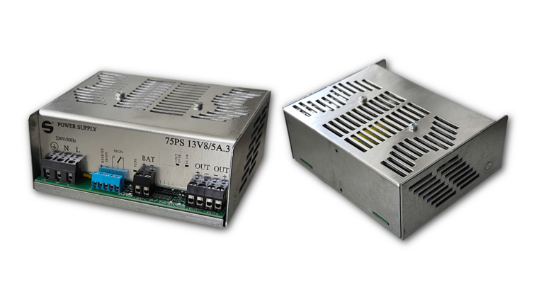
The power supplies are designed for general-purpose use to power electrical and electronic devices with DC voltage in indoor environments without explosive hazards. The output voltage range is from 4.2 V to 55.2 V. The unit is designed for DIN rail mounting, but can also be secured with screws using a flange (flange must be ordered separately).
The nominal output voltages and corresponding maximum output currents are listed in the table. The power supply is protected against output short circuits. Input and output wiring is connected via screw terminals. The input and output terminals are not protected against contact with hazardous voltage. Protection of the input terminals must be ensured by the customer.
Table 1: Technical parameters
| Input Voltage | 195 - 255 V AC |
| Operating temperature | -15°C to +40 °C |
| Operating Relative Humidity | Max. 75% non-condensing |
| Efficiency (typical) | 85% |
| Output short-circuit protection | Yes – self-resetting |
| Surge protection | Yes, max. 135% of output voltage |
| Dielectric Strength | Output – PE min. 500 V DC |
| Option to connect the output negative pole to PE | Yes |
| Option for series connection | Yes |
| Option for parallel connection | Yes |
| Operating frequency | 25 - 60 kHz |
| Dimensions | 120 × 102 × 48 mm |
| Weight | 540 g |
Table 2: Documents
Table 4: 75PS Power Supply Models
| Model Name | Output Voltage | Output Current | Stability | Ripple | Noise |
| 75PS04V2/7A.x | 4,2 V | 7 A | <2 % | <20 mV | <50 mV šš |
| 75PS05V/7A.x | 5 V | 7 A | <2 % | <20 mV | <50 mV šš |
| 75PS06V/7A.x | 6 V | 7 A | <2 % | <20 mV | <50 mV šš |
| 75PS06V9/7A.x | 6.9 V | 7 A | <2 % | <20 mV | <50 mV šš |
| 75PS09V/7A.x | 9 V | 7 A | <2 % | <20 mV | <50 mV šš |
| 75PS10V/7A.x | 10 V | 7 A | <2 % | <20 mV | <50 mV šš |
| 75PS12V/6A.x | 12 V | 6 A | <2 % | <20 mV | <50 mV šš |
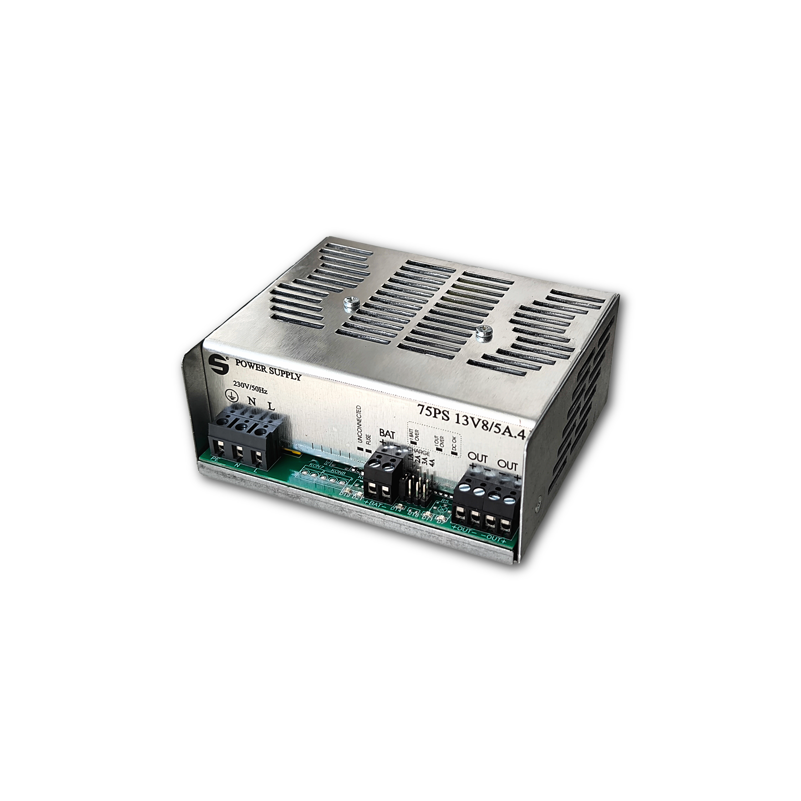
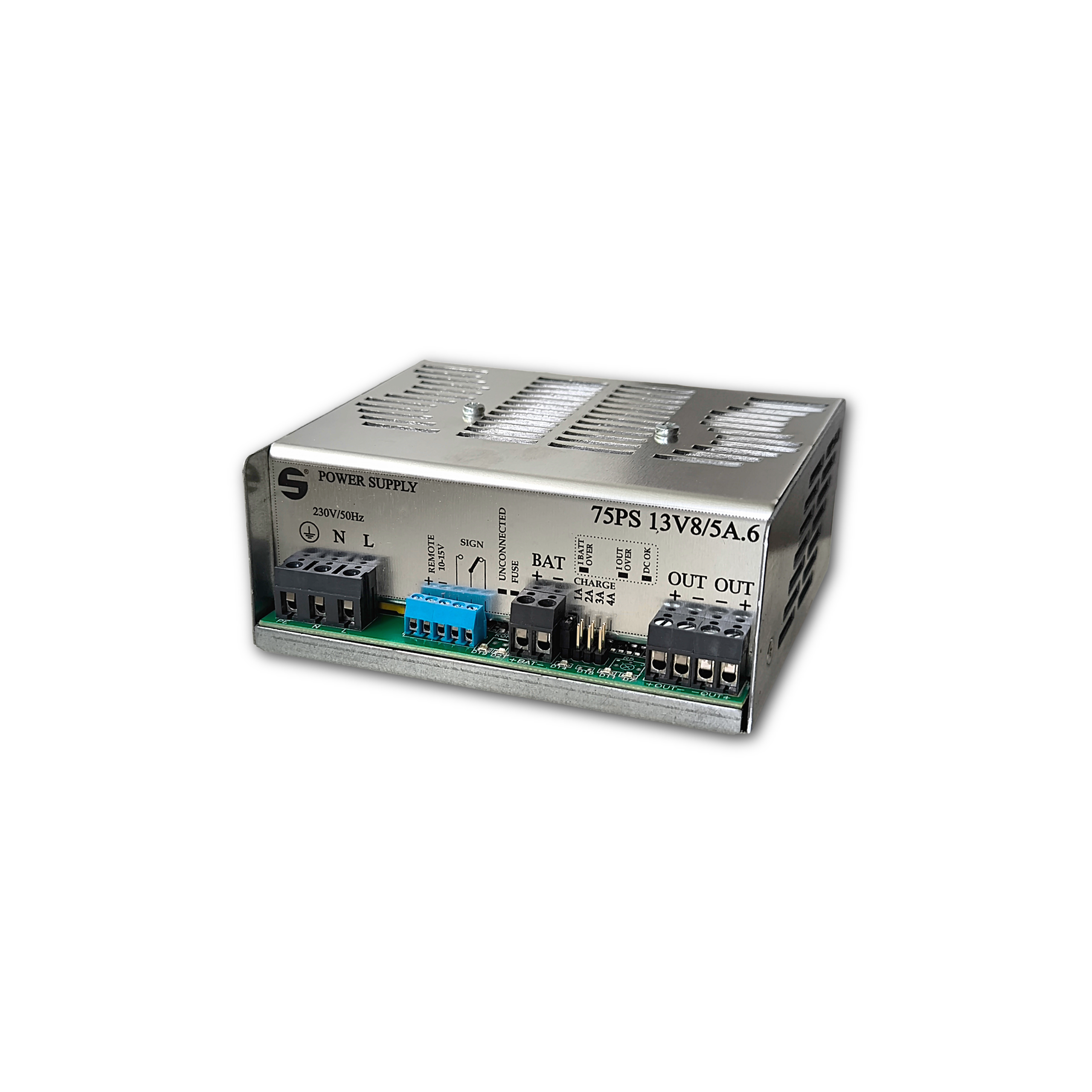
| 75PS13V8/5A.x | 13.8 V | 5 A | <2 % | <20 mV | <50 mV šš |
| 75PS15V/5A.x | 15 V | 5 A | <2 % | <20 mV | <50 mV šš |
| 75PS16V/4A5.x | 16 V | 4,5 A | <2 % | <20 mV | <50 mV šš |
| 75PS17V/4A.x | 17 V | 4 A | <2 % | <20 mV | <50 mV šš |
| 75PS18V/4A.x | 18 V | 4 A | <2 % | <20 mV | <50 mV šš |
| 75PS20V7/3A5.x | 20,7 V | 3,5 A | <2 % | <20 mV | <50 mV šš |
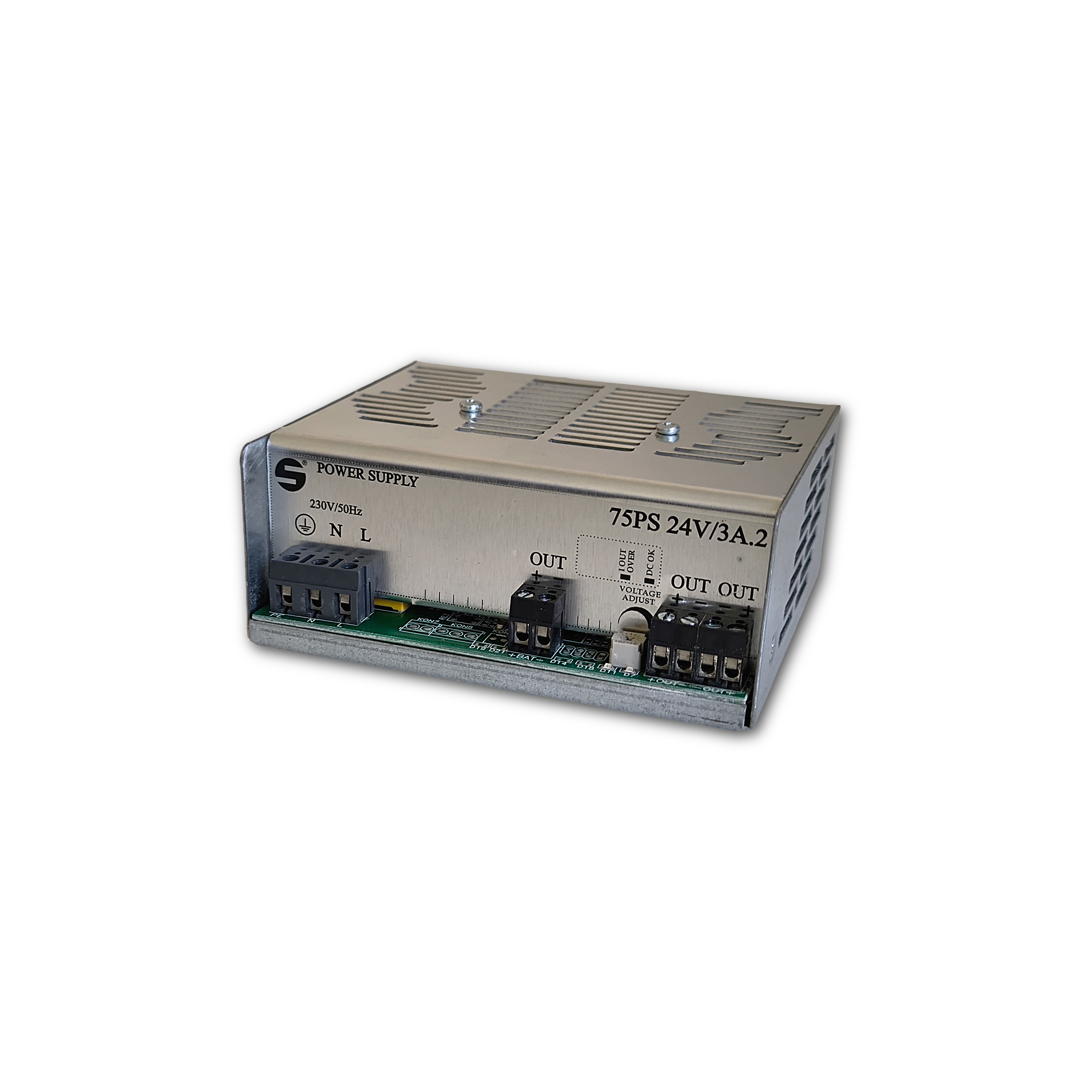
| 75PS24V/3A.x | 24 V | 3 A | <2 % | <20 mV | <50 mV šš |
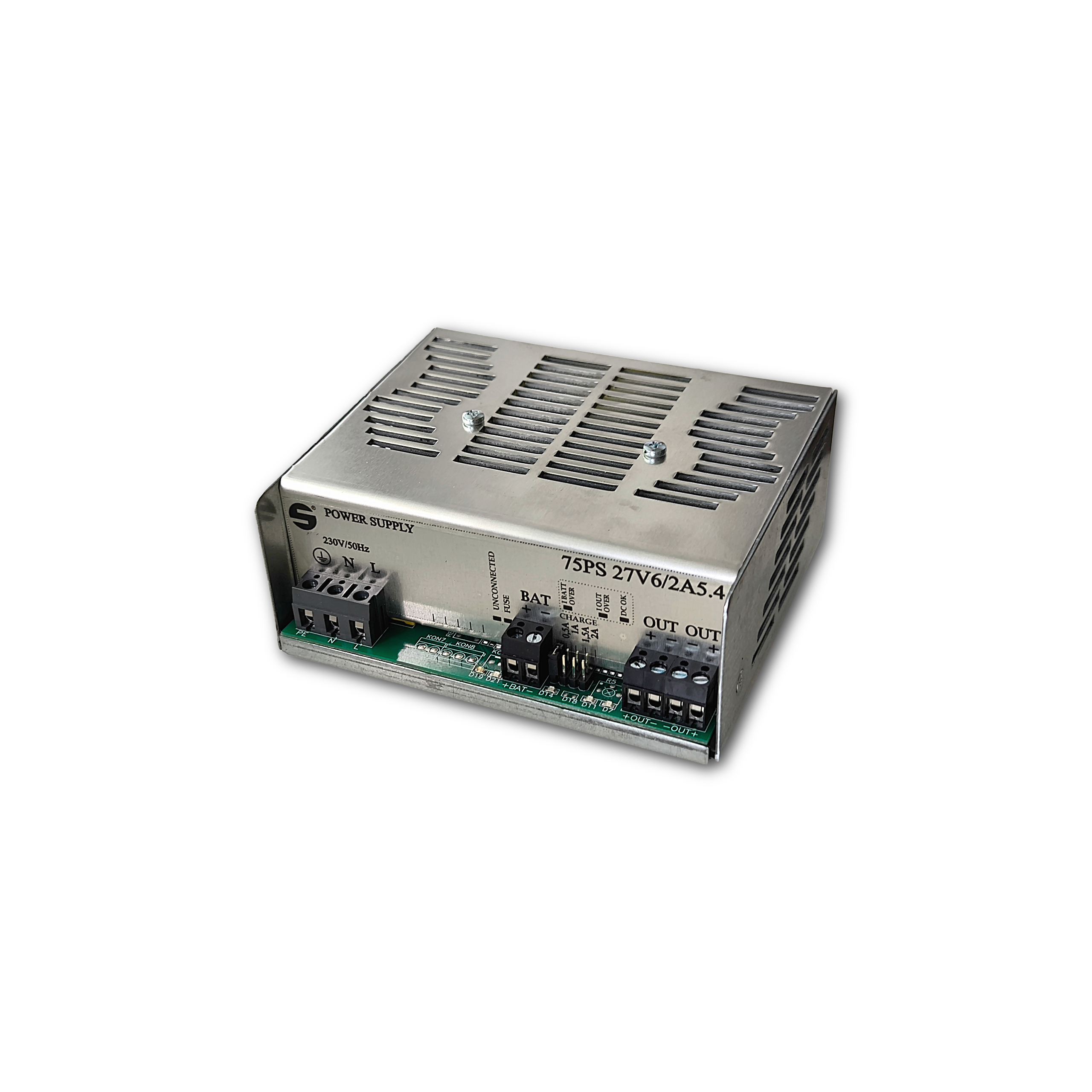
| 75PS27V6/2A5.x | 27.6 V | 2.5 A | <2 % | <20 mV | <50 mV šš |
| 75PS48V/1A5.x | 48 V | 1,5 A | <2 % | <20 mV | <50 mV šš |
| 75PS55V2/1A3.x | 55,2 V | 1,3 A | <2 % | <20 mV | <50 mV šš |
.x – the digit specifies the type of added functions (see below)
Additional Power Supply Functions (Designation .x):

Description of Additional Functions:
Disconnect function - The disconnector serves as protection against deep discharge of the battery. This means that when the voltage at its output terminals drops below 10.5 V (21 V), it disconnects the battery from the circuit (galvanically disconnecting the positive pole). Any further drop would cause irreversible damage to the battery, requiring its replacement, while the energy it can still deliver at this voltage is very low and the voltage drops rapidly. Battery Charging Current Setting - This function is used to set the maximum charging current for the battery in five steps by inserting a jumper into the corresponding position. Note that this circuit does not limit the current the battery can deliver to the load. For 13.8 V units: 1 A, 2 A, 3 A, 4 A, and 4.5 A. For 27.6 V units: 0.5 A, 1 A, 1.5 A, 2 A, and 2.25 A. The last value represents the maximum current if the jumper is not inserted or is damaged. When setting the maximum charging current, it is recommended to consider the battery manufacturer's maximum charging current specifications and the circuit’s current ratings. Status Signaling - Galvanically connected: During operation, a voltage of approximately 10 V is present at the output terminals. The negative pole is connected to the negative pole of the output voltage. External Shutdown Applying a voltage of 10–15 V to the terminals will shut down the power supply without the need to disconnect the AC input. The input is galvanically isolated by an optocoupler with a dielectric strength of 5 kV. Blown Fuse Signaling - If the fuse is blown while the power supply is switched on, a red LED will light up. |